Difference between revisions of "GEM1305-ardupilot"
| (22 intermediate revisions by the same user not shown) | |||
| Line 4: | Line 4: | ||
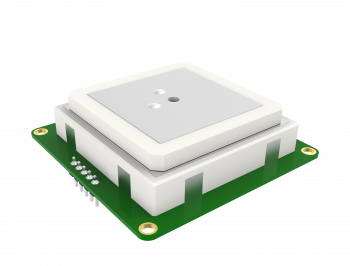
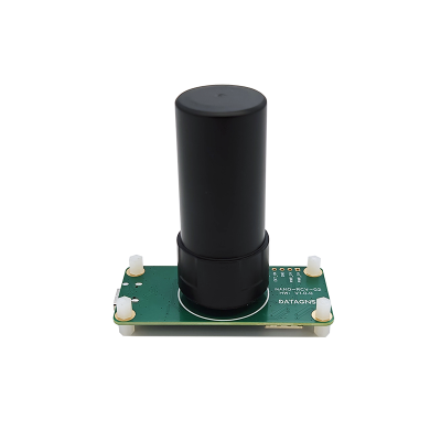
GEM1305 is a RTK receiver with antenna designed and manufactured by DATAGNSS. | GEM1305 is a RTK receiver with antenna designed and manufactured by DATAGNSS. | ||
It is based on the new generation Allystar dual-core GNSS SoC. It supports RTK functionality with a maximum data update rate of 5Hz. | |||
GEM1305/NANO RTK Receiver doesn't support Moving Base mode. | GEM1305/NANO RTK Receiver doesn't support Moving Base mode. | ||
[[File:GEM1305-1-v2.png|350px|frameless|GEM1305 dual-band RTK smart antenna]] | |||
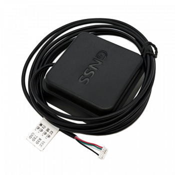
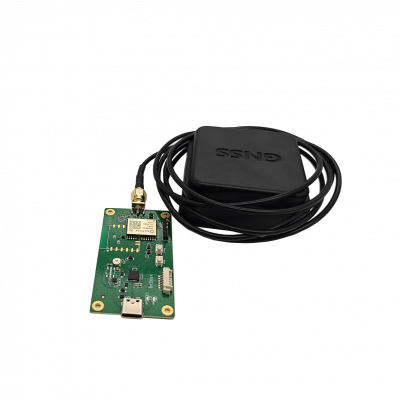
GEM1305 also has a version with a casing. | GEM1305 also has a version with a casing. | ||
[[File:DGM10-A01-main.png|350px|frameless|GEM1305 dual-band RTK smart antenna]] | |||
=== Key Features === | === Key Features === | ||
| Line 17: | Line 21: | ||
* High performance antenna | * High performance antenna | ||
GNSS | === Specifications === | ||
==== | ==== Frequencies ==== | ||
* GPS/QZSS: L1 C/A, L5C | |||
* GLONASS: L1OF | |||
* BEIDOU: B1I, B2a | |||
* GALILEO: E1, E5a | |||
==== GNSS ==== | |||
* Allystar CYNOSURE IV GNSS SOC | |||
* Dual core | |||
* 3D accuracy: 1.5m CEP | |||
* RTK accuracy: 1cm +1PPM(H), 3cm+1PPM(V) | |||
==== Interface ==== | |||
* UART, 230400bps default | |||
* SMA connector for antenna | |||
* Output rate 5Hz default | |||
* Main power supply,4.7~5.2V | |||
==== Protocol ==== | |||
======== | * NMEA-0183 output | ||
* RTCMv3 input/output | |||
==== Environment ==== | |||
* Operating temp. -20~85℃ | |||
==== Dimession and weight ==== | |||
* 55*55*12mm | |||
* 50g (GEM1305) 26g (NANO with Helix) | |||
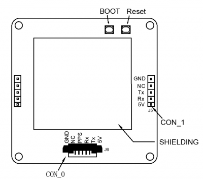
==== Pin Map ==== | |||
The board is connected to the autopilot via UART interface. | The board is connected to the autopilot via UART interface. | ||
[[File:GEM1305-connector.png|400px|frameless|GEM1305 connector]] | |||
Please note that the board only includes RTK and doesn't inlcude compass. | Please note that the board only includes RTK and doesn't inlcude compass. | ||
| Line 73: | Line 63: | ||
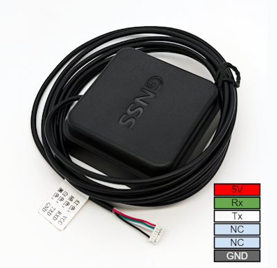
If using the GEM1305 with a case, you can directly insert the connector into the GPS2 port. | If using the GEM1305 with a case, you can directly insert the connector into the GPS2 port. | ||
[[File:GEM1305-with-case.png|400px|frameless|GEM1305 with case]] | |||
=== ArduPilot Setup === | |||
Assuming GEM1305 is connected to the autopilot's SERIAL4 port, it should work with : | Assuming GEM1305 is connected to the autopilot's SERIAL4 port, it should work with : | ||
- | [[https://ardupilot.org/dev/docs/AP_Periph-Parameters.html#serial4-protocol-serial4-protocol-selection SERIAL4_PROTOCOL]] = 5 | ||
=== Configuration === | |||
RTK technology can greatly improve the accuracy of positioning. | RTK technology can greatly improve the accuracy of positioning. | ||
| Line 95: | Line 82: | ||
The data from the base needs to be transmitted to the drone via telemetry radio and inputted into the RTK receiver on the rover. | The data from the base needs to be transmitted to the drone via telemetry radio and inputted into the RTK receiver on the rover. | ||
[[File:setup-rtk-00.png|800px|frameless]] | |||
=== | === Base station setup === | ||
We suggest using the NANO RTK Receiver as the configuration for the base station(ground base station), which is more convenient and user-friendly. | We suggest using the NANO RTK Receiver as the configuration for the base station(ground base station), which is more convenient and user-friendly. | ||
[[File:nano-rtk-rcv-helix.png|400px|frameless]] | |||
[[File:nano-rtk-rcv-patchAnt.png|400px|frameless]] | |||
Connect the NANO RTK Receiver to your Laptop via USB. | Connect the NANO RTK Receiver to your Laptop via USB. | ||
| Line 114: | Line 97: | ||
Setup the NANO RTK Receiver as a base station, and it is recommended to use Satrack software. | Setup the NANO RTK Receiver as a base station, and it is recommended to use Satrack software. | ||
*[https://wiki.datagnss.com/images/e/ee/Satrack.zip Download Satrack v1.30.016] | |||
1. Open Satrack, then choose the com port, baud rate then connect the nano-rtk-rcv. | 1. Open Satrack, then choose the com port, baud rate then connect the nano-rtk-rcv. | ||
[[File:satrack-connect-device.png|300px|frameless]] | |||
2. Enable RTCMv3 output | 2. Enable RTCMv3 output | ||
[[File:satrack-rtcm-output.png|300px|frameless]] | |||
3. Disable NMEA data output | 3. Disable NMEA data output | ||
[[File:satrack-disable-nmea.png|300px|frameless]] | |||
4. Config output rate to 1Hz | 4. Config output rate to 1Hz | ||
In base station mode, the RTCM data output rate must be set to 1Hz. | |||
[[File:atrack-outputrate-1hz.png|300px|frameless]] | |||
5. Config the base station fixed coordinates | 5. Config the base station fixed coordinates | ||
There are two methods to set the coordinates of the base station: | |||
5.1 According to the diagram below, Input the known coordinates. | |||
Press "Get now", and modify the coordinates to the known values, then "send" to apply the fixed coordinates. | |||
[[File:satrack-cfg-fixedecef.png|300px|frameless]] | |||
5.2 According to the CFG-SURVEY method, config miniDuration and AccLimit, then automatically calculate the average before proceeding with the setup. | |||
[[File:satrack-cfg-survey.png|300px|frameless]] | |||
After completing the above operation, you can save the current configuration with CFG-SAVE. | |||
6. After above configuration, open Mission Planner | 6. After above configuration, open Mission Planner | ||
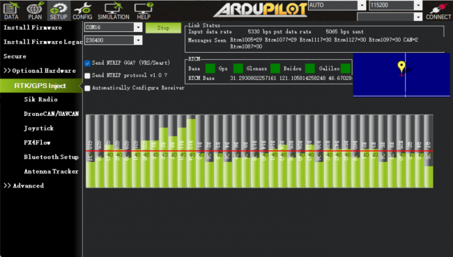
[[File:mp-connect-base.png|650px|frameless]] | |||
7. Finish other configuration in Mission Planner | 7. Finish other configuration in Mission Planner | ||
=== Rover station (Aircraft) setup === | |||
Rover station (Aircraft) setup | |||
For drones, NANO RTK Receiver or GEM1305 can be chosen as the Rover for RTK. | For drones, NANO RTK Receiver or GEM1305 can be chosen as the Rover for RTK. | ||
* Please note that NANO RTK Receiver supports Ardupilot starting from V3.0. | |||
Whether you choose NANO RTK Receiver or GEM1305, you need to confirm in the Satrack software that all RTCM data outputs are disabled and all NMEA outputs are enabled. | Whether you choose NANO RTK Receiver or GEM1305, you need to confirm in the Satrack software that all RTCM data outputs are disabled and all NMEA outputs are enabled. | ||
| Line 183: | Line 154: | ||
After completing the above settings, you can write parameters to the flight controller. | After completing the above settings, you can write parameters to the flight controller. | ||
=== Package List === | |||
* GEM1305 RTK Receiver | |||
* DG-6P-C01,GH-1.25mm-6P cable | |||
Latest revision as of 16:40, 23 October 2024
Overview
This page mainly includes some instructions for using the GEM1305 and NANO RTK Receiver products with Ardupilot.
GEM1305 is a RTK receiver with antenna designed and manufactured by DATAGNSS.
It is based on the new generation Allystar dual-core GNSS SoC. It supports RTK functionality with a maximum data update rate of 5Hz.
GEM1305/NANO RTK Receiver doesn't support Moving Base mode.
GEM1305 also has a version with a casing.
Key Features
- Full constellation, multi-frequency GNSS satellite receiver
- Support RTK
- Standard UART serial interface
- Lightweight only 50g or 26g(NANO RTK receiver)
- High performance antenna
Specifications
Frequencies
- GPS/QZSS: L1 C/A, L5C
- GLONASS: L1OF
- BEIDOU: B1I, B2a
- GALILEO: E1, E5a
GNSS
- Allystar CYNOSURE IV GNSS SOC
- Dual core
- 3D accuracy: 1.5m CEP
- RTK accuracy: 1cm +1PPM(H), 3cm+1PPM(V)
Interface
- UART, 230400bps default
- SMA connector for antenna
- Output rate 5Hz default
- Main power supply,4.7~5.2V
Protocol
- NMEA-0183 output
- RTCMv3 input/output
Environment
- Operating temp. -20~85℃
Dimession and weight
- 55*55*12mm
- 50g (GEM1305) 26g (NANO with Helix)
Pin Map
The board is connected to the autopilot via UART interface.
Please note that the board only includes RTK and doesn't inlcude compass.
If using the GEM1305 with a case, you can directly insert the connector into the GPS2 port.
ArduPilot Setup
Assuming GEM1305 is connected to the autopilot's SERIAL4 port, it should work with :
[SERIAL4_PROTOCOL] = 5
Configuration
RTK technology can greatly improve the accuracy of positioning.
RTK technology requires a base and a rover, with the base placed on the ground, which is referred to as the rover on the drone.
The data from the base needs to be transmitted to the drone via telemetry radio and inputted into the RTK receiver on the rover.
Base station setup
We suggest using the NANO RTK Receiver as the configuration for the base station(ground base station), which is more convenient and user-friendly.
Connect the NANO RTK Receiver to your Laptop via USB.
Setup the NANO RTK Receiver as a base station, and it is recommended to use Satrack software.
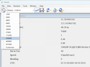
1. Open Satrack, then choose the com port, baud rate then connect the nano-rtk-rcv.
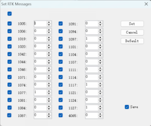
2. Enable RTCMv3 output
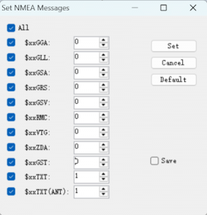
3. Disable NMEA data output
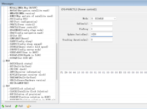
4. Config output rate to 1Hz
In base station mode, the RTCM data output rate must be set to 1Hz.
5. Config the base station fixed coordinates
There are two methods to set the coordinates of the base station:
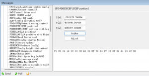
5.1 According to the diagram below, Input the known coordinates.
Press "Get now", and modify the coordinates to the known values, then "send" to apply the fixed coordinates.
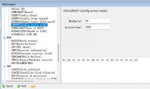
5.2 According to the CFG-SURVEY method, config miniDuration and AccLimit, then automatically calculate the average before proceeding with the setup.
After completing the above operation, you can save the current configuration with CFG-SAVE.
6. After above configuration, open Mission Planner
7. Finish other configuration in Mission Planner
Rover station (Aircraft) setup
For drones, NANO RTK Receiver or GEM1305 can be chosen as the Rover for RTK.
- Please note that NANO RTK Receiver supports Ardupilot starting from V3.0.
Whether you choose NANO RTK Receiver or GEM1305, you need to confirm in the Satrack software that all RTCM data outputs are disabled and all NMEA outputs are enabled.
In Rover mode, the output rate must be set to 5Hz.
Note: NANO RTK Receiver and GEM1305 do not support safety switch, so BRD_SAFETY_DEFLT needs to be set to 0 or a separate safety switch should be connected to the flight controller.
After completing the above settings, you can write parameters to the flight controller.
Package List
- GEM1305 RTK Receiver
- DG-6P-C01,GH-1.25mm-6P cable
