Difference between revisions of "Multiband-antenna-for-rtk"
| (8 intermediate revisions by the same user not shown) | |||
| Line 1: | Line 1: | ||
== Multi-band antenna for RTK application == | == Multi-band antenna for RTK application == | ||
__NOTOC__ | |||
[[File:AGR6302G-1.png|300px|thumb|AGR6302G Patch antenna]] | |||
The increasing demand for highly accurate positioning has led to a growing need for receiving a greater number of GNSS satellites. This has resulted in a trend towards using multi-band GNSS systems. Selecting an appropriate antenna is crucial as it serves as the primary link between the GNSS space segment and users, particularly in multi-band systems. | |||
AGR6302G is designed for RTK applications | The AGR6302G antenna is specifically designed for RTK applications and supports GPS, BDS (BeiDou), Galileo, GLONASS, IRNSS (NavIC), and QZSS systems. For more details, please refer to Table 1. This antenna offers stable signal quality and improved reception angles under practical conditions. It utilizes a stacked four-feed antenna architecture with hybrid technology to enable multi-band operation while achieving lower axial ratio, wider half-power beam width, and excellent right-hand circular polarization. | ||
hand circular polarization. | |||
In terms of its internal structure, this antenna incorporates two stages in its active component: one-level filter and one low-noise amplifier (LNA) for each lower/higher band path. The combined output of dual filters and a second-level LNA provides RF gain to the receiver. This design ensures excellent noise figure/RFL linear characteristics along with high LNA gain and out-of-band rejection capabilities. As a result, it delivers a good signal-to-noise ratio while minimizing interference. | |||
The AGR6302G antenna is housed in a compact industrial-grade waterproof enclosure that allows for flexible installation options nearly anywhere. By using an SMA connector compatible with GNSS modules or receivers, it showcases its multi-band RTK performance effectively. | |||
== Mechenical specs == | == Mechenical specs == | ||
| Line 13: | Line 14: | ||
{| class="wikitable" | {| class="wikitable" | ||
|- | |- | ||
! style="background-color:#9b9b9b;" | | ! style="background-color:#9b9b9b;" | Item | ||
! style="background-color:#9b9b9b;" | | ! style="background-color:#9b9b9b;" | Specs | ||
|- | |- | ||
| Weight | | Weight | ||
| Line 132: | Line 133: | ||
== Antenna dimensions == | == Antenna dimensions == | ||
[[File:AG-for-rtk.png|frameless|500px|Multiband rtk antenna]] | [[File:AG-for-rtk-1.png|frameless|500px|Multiband rtk antenna]] | ||
Latest revision as of 16:50, 4 November 2024
Multi-band antenna for RTK application
The increasing demand for highly accurate positioning has led to a growing need for receiving a greater number of GNSS satellites. This has resulted in a trend towards using multi-band GNSS systems. Selecting an appropriate antenna is crucial as it serves as the primary link between the GNSS space segment and users, particularly in multi-band systems.
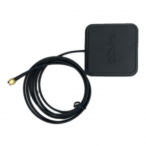
The AGR6302G antenna is specifically designed for RTK applications and supports GPS, BDS (BeiDou), Galileo, GLONASS, IRNSS (NavIC), and QZSS systems. For more details, please refer to Table 1. This antenna offers stable signal quality and improved reception angles under practical conditions. It utilizes a stacked four-feed antenna architecture with hybrid technology to enable multi-band operation while achieving lower axial ratio, wider half-power beam width, and excellent right-hand circular polarization.
In terms of its internal structure, this antenna incorporates two stages in its active component: one-level filter and one low-noise amplifier (LNA) for each lower/higher band path. The combined output of dual filters and a second-level LNA provides RF gain to the receiver. This design ensures excellent noise figure/RFL linear characteristics along with high LNA gain and out-of-band rejection capabilities. As a result, it delivers a good signal-to-noise ratio while minimizing interference.
The AGR6302G antenna is housed in a compact industrial-grade waterproof enclosure that allows for flexible installation options nearly anywhere. By using an SMA connector compatible with GNSS modules or receivers, it showcases its multi-band RTK performance effectively.
Mechenical specs
| Item | Specs |
|---|---|
| Weight | ≤200g |
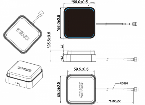
| Dimensions | 66.0*66.0*25.6 |
| Cable type | RG174 |
| Connector type | SMA |
| Cable length | 1500mm(customizable) |
| Mount | Magnet |
| Salt spray test | 48H |
| Waterproof and dustproof | IP65 |
Environment Feature
| Item | Specs |
|---|---|
| Temperature(Typical) | -40℃~+70℃ |
| Temperature(Max) | -40℃~+85℃ |
| Humidity | 10 to 95% RH |
Electrical performance
The electrical performance of the samples described in this document was measured under specific conditions:
- temperature: 25±15℃
- humidity: 65±20%RH
- instrument power setting: 1uW
- air pressure: (0.96±0.1) X 105 Pa
all experimental data were obtained by measuring with a block antenna connected to a grounding plate measuring 70*70mm, inside a microwave darkroom.
Antenna(Patch)Specs
| Items | Specs |
|---|---|
| Frequency Range | GPS L1/L2/L5
BDS B1/B2/B3 GLONASS G1/G2 GALILEO E1/E5a/E5b |
| Bandwidth | ≥100MHz |
| Gain | ≥4 dBic typ (@70*70 Ground) |
| S.W.R | ≤2.0 |
| Polarization | Right-hand circular polarization(RHCP) |
| Axial ratio | ≤3 dB |
LNA Performance
| Items | Specs | |
|---|---|---|
| Gain | GPS L1/L2/L5
BDS B1/B2/B3 GLONASS G1/G2 GALILEO E1/E5a/E5b |
28.0±3dB |
| Noise Figure | 2.0 dB typ | |
| Input standing wave | ≤2.0 | |
| Output standing wave | ≤2.0 | |
| Voltage | DC 3.0~5.0V | |
| Current | ≤60mA (@3.3V) | |
| Impedance | 50Ω | |

