GEM1111
GEM1111 - 1616A00
1. Overview
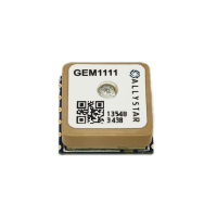
GEM1111 is a high-performance L1 GNSS positioning module with antenna built-in, which is developed on the base of the state-of-the-art Allystar Cynosure III Lite architecture.
It supports global civil navigation systems, including GPS, BDS, GLONASS, Galileo, and QZSS. Featured with SAW and LNA, GEM1111 achieves high positioning accuracy and short TTFF,
especially in a rough urban environment.
It supports antenna supervisor and auto-switching between the built-in antenna and the external antenna.
With a compact body and high performance, GEM1111 is widely applied to tracking applications, like automotive, consumer, and industrial tracking.
1.2 Feature
- Supports GPS, BDS, Galileo, GLONASS, and QZSS systems Built-in LNA & SAW for better sensitivity
- Supports A-GNSS
- Supports geo-fence function
- Ultra-low power consumption around 13 mA in tracking mode
- Supports antenna supervision
- Supports auto-switching between the built-in antenna and the external antenna
1.1 Specifications
| Parameters | Specification |
|---|---|
| GNSS tracking channels | 72 channels, GPS/QZSS: L1C/A Galileo: E1 GLONASS: L1 |
| Updating rate | 1 Hz (Default), up to 5 Hz |
| Position accuracy | < 1.5 m CEP @ Open Sky |
| Velocity accuracy | 0.1 m/s CEP |
| Time accuracy | 1PPS 20ns |
| Time to First Fix(TTFF) | Hot start 1S Cold star 28S |
| Sensitivity | Cold start -149 dBm Reacquisition -159dBm Tracking -163dBm |
| Power supply | 2.0-3.63 V, Typical 3.3 V |
| Power consumption | Acquisition 15mA @3.3V Tracking 13mA @3.3V Standby mode 10uA |
| Serial Interface | UART Default: 115200 bps |
| Protocol | NMEA 0183 Protocol Ver.3.01/4.00 (Default)/4.10 |
| Operating temperature | -40~+85℃ |
| Storage temperature | -40~+85℃ |
| Weight | 7.5g |
| Dimessions | 16*16*6.9mm |
2.Pin description
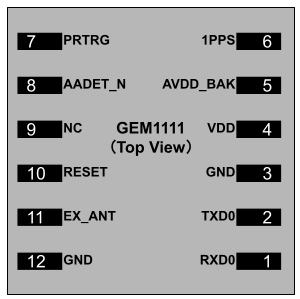
2.1 Pin assignment
2.2 Detailed pin description
| Function | Symbol | No | I/O | Decription |
|---|---|---|---|---|
| Power | VDD | 4 | Power | Main power supply voltage input. |
| GND | 3,12 | VSS | Ground | |
| AVDD_BAK | 5 | Power | Backup power supply voltage input. Backup power is needed in order to enable warm and hot start features. Backup power is a must for the system to work. If no backup power is available, connect AVDD_BAK to the main power supply. | |
| Antenna | RF_IN | 11 | I | RF signal input. Use a controlled impedance of 50 for the routing from RF_IN pin to the antenna or the antenna connector. |
| UART | TXD0 | 2 | O | UART0 serial data Tx. |
| RXD0 | 1 | I | UART0 serial data Rx. | |
| Other | PRTRG | 7 | I | Mode selection or the trigger input in deep sleep mode to wake up the system. |
| RESET | 10 | I | External reset, low active | |
| 1 PPS | 6 | O | Setting for time pulse output (PPS). Leave it floating if not used. | |
| AADET_N | 8 | O | Active antenna detection | |
| NC | 9 | Reserved. Leave it floating if not used. |
3.ELECTRICAL CHARACTERISTICS
3.1 Absolute Maximum Rating
| Symbol | Parameter | Min. | Max. | Unit |
|---|---|---|---|---|
| VDD | Power input for the main power domain | -0.5 | 3.6 | V |
| AVDD_BAK | Power input for the backup power domain | -0.5 | 3.6 | V |
| VImax | Digital I/O pin input voltage | -0.5 | 3.6 | V |
| Tstorage | Storage temperature | -40 | 85 | °C |
| Tsolder | Solder reflow temperature | -- | 260 | °C |
3.2 IO Characteristics
3.2.1 PRRSTX and PRTRG
| Symbol | Parameter | Condition | Min. | Typ. | Max. | Unit |
|---|---|---|---|---|---|---|
| IIZ | Input leakage current |
-- | -- | -- | +/-1 | uA |
| VIH | Input high voltage | -- | AVDD_BAK*0. 67 | -- | AVDD_BAK | V |
| VIL | Input low voltage | -- | 0 | -- | AVDD_BAK*0.27 | V |
| VOH | Output high voltage |
IOH=5.3 mA, AVDD_BAK=3.3V |
2.64 | -- | -- | V |
| IOH=1.2 mA, AVDD_BAK=1.8V |
1.53 | -- | -- | V | ||
| VOL | Output low voltage | IOL=3.9 mA, AVDD_BAK=3.3V |
-- | -- | 0.4 | V |
| IOL=1.9 mA, AVDD_BAK=1.8V |
-- | -- | 0.45 | V | ||
| Ci | Input capacitancee | -- | -- | -- | 11 | pF |
| RPU | Pull-up resistance | -- | 35 | -- | 84 | kΩ |
3.2.2 Others
| Symbol | Parameter | Condition | Min. | Typ. | Max. | Unit |
|---|---|---|---|---|---|---|
| IIZ | Input leakage current | -- | -- | -- | +/-1 | uA |
| VIH | Input high voltage | -- | VDD*0.67 | -- | VDD | V |
| VIL | Input low voltage | -- | 0 | -- | VDD*0.27 | V |
| VOH | Output high voltage | IOH =5.3 mA, VDD=3.3V | 2.64 | -- | -- | V |
| VOL | Output low voltage | IOL =3.9 mA, VDD=3.3V | -- | -- | 0.4 | V |
| Ci | Input capacitance | -- | -- | -- | 11 | pF |
3.3 DC Characteristics
3.3.1 Operating Conditions
| Symbol | Parameter | Min. | Typ. | Max. | Unit |
|---|---|---|---|---|---|
| VDD | Power supply voltage | 3.0 | 3.3 | 3.6 | V |
| AVDD_BAK | Backup battery voltage | 1.6 | 3.3 | 3.6 | V |
| ICCmax | Maximum operating current @ VDD | -- | -- | 200 | mA |
| Tenv | Operating temperature | -40 | -- | 85 | °C |
3.3.2 Power Consumption
| Parameter | Measure Pin | Typ. | Unit |
|---|---|---|---|
| Average tracking current(GNSS) | VDD[1] | 33 | mA |
| Standby mode | AVDD_BAK[2] | 14 | uA |
- [1] Condition: VDD=3.3V@Room Temperature. All Pins Open. GNSS=GPS+Galileo+GLONASS+QZSS+SBAS
- [2] Condition: AVDD_BAK=3.3V@Room Temperature. All Pins Open.
4. HARDWARE DESCRIPTION
4.1 Connecting Power
In order to ensure positioning performance, please control the ripple of the module power supply.
It is recommended to use the LDO with a max output current above 100mA.
If the power for the VDD pin is off, the real-time clock (RTC) and battery-backed RAM (BBR) is supplied through the AVDD_BAK pin. Thus, orbit information and time can be maintained and will allow a Hot or Warm start.
Note: If no backup supply is available, connect the AVDD_BAK pin to the main power supply. The floating state is not recommended.
4.2 Internal Antenna
GEM1111-1818A00 provides a 18x18mm internal antenna.
4.3 Reset and Mode control
The operation mode of the GNSS module is controlled by PRRSTX (nRESET) and PRTRG (BOOT) pin.
While the module works in normal operation, leave PRRSTX and PRTRG pins floating if there is no upgrading or reset demands, or others.
Keep PRTRG pin floating during system power-up or the external reset (PRRSTX from low to high), and the module will enter User Normal Mode.
When the module powers up or PRRSTX from low to high, the module will execute an external reset. (If the power for AVDD_BAK is always on, the external reset will not affect the ephemeris data in the backup domain)
Drive PRTRG pin to low or connect PRTRG to GND directly (not by pull-down resistance) during system power-up or the external reset (PRRSTX from low to high),
and the system enters BootROM Command Mode at PRTRG pin being released from low to floating state, and ready for firmware upgrading command.
When connecting PRRSTX and PRTRG to any host IO, DO NOT use the pull-up or pull-down resistance.
4.4 Default Serial Interfaces
| Interface | Settings |
|---|---|
| UART output | 115200 baud, 8 data bits, no parity bit, 1 stop bit. Configured to transmit both NMEA and HD Binary protocols, but only the following NMEA (and no HD Binary sentence) messages have been activated at start-up: GGA, GSA, GSV, RMC, ZDA, TXT-ANT |
| UART input | 115200 baud, 8 data bits, no parity bit, 1 stop bit, autobaud disabled. Automatically accepts the following protocols without the need for explicit configuration: HD binary sentence, NMEA The GNSS receiver supports interleaved HD Binary and NMEA messages. |
| Timepulse (1Hz Nav) |
1 pulse per second, synchronized at the rising edge, pulse length 100ms. |
When the module is applied to the specific application, users can shut off the main power in order to further reduce the power consumption.
To avoid the high level of serial interface influencing the normal operation, it is highly suggested to cut off the serial port when shutting off the main power.
Otherwise, please set the serial port to input mode or high impedance state with a pull-down resistor.
Datasheet
DATASHEET offline file is not always the latest version, you can find it here.
Resource
Common_Commands_Exclusive_to_Allystar

