TAU1312
TAU1312 - 1216A00
1.Overview
Feature
- Supports GPS, BDS, GLONASS, Galileo, and QZSS
- Compact size for high precision industry
- Integrated Real Time Kinematics (RTK)
- State-of-art low power consumption
- Supports multi-band multi-system high-precision raw data output, easy for 3rd party integration
- Highly integrated module, the best cost-effective high precision GNSS solution
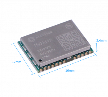
- Compact size 12*16mm
Product photo
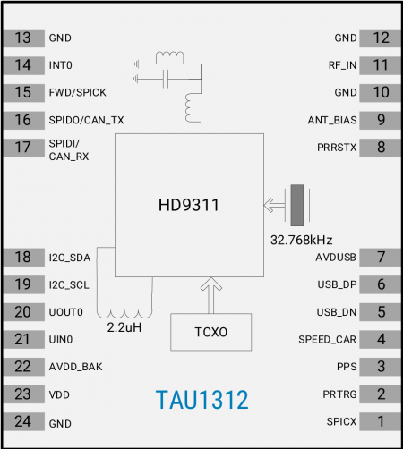
Block diagram
Specifications
| Parameter | Specifications | ||
|---|---|---|---|
| Constellations | BDS, GPS, QZSS, GLONASS, Galileo, NavIC, SBAS | ||
| Channel | 40 | ||
| Update rates | PVT 10Hz RTK 5Hz Max | ||
| Position accuracy | GNSS | 2.5m CEP | |
| SBAS | <1.0m CEP | ||
| RTK | 1.5 cm + 1 ppm (H) 6.5 cm + 1 ppm (V) | ||
| Velocity & Time accuracy | GNSS | 0.1 m/s CEP | |
| 1PPS | 20ns RMS | ||
| TTFF | Hot start | 2s | |
| Cold start | 24s | ||
| RTK | Convergence time | <10s | |
| Reliability | >99.9% | ||
| Sensitivity | Cold start | -148 dBm | |
| Hot start | -158 dBm | ||
| Reacquisition | -160 dBm | ||
| Tracking & navigation | -162 dBm | ||
| Protocol | NMEA-0183 V4.00/4.10 | ||
| RTCM 3.X,raw measurements | |||
| Baudrate | 115200 bps, by default,max up to 460800bps | ||
| Operating condition | Main supply | 2.0V to 3.6V | |
| Digital I/O supply | 1.8V to 3.6V | ||
| Backup supply | 1.8V to 3.6V | ||
| Power consumption | Tracking | GNSS | 34 mA @ 3.3V |
| Single system | 22 mA @ 3.3V | ||
| Standby | Data backup | 12 uA | |
| RTC | 1.4 uA | ||
| Serial interface | UART | 1 | |
| SPI | 1[*] | ||
| I2C | 1[*] | ||
| Operating limit | Velocity | 515 m/s | |
| Altitude | 18,000m | ||
| Environmental conditions | Operating temp. | -40°C to +85°C | |
| Storage temp. | -40°C to +90°C | ||
| Humidity | 95% RH | ||
| Size | 16.0×12.2×2.4 mm, 24pin LCC | ||
Table 2 specifications
[*] upon specific firmware
GNSS Reception
Table 3 GNSS reception table
| P/N | OPTIONS | GPS/QZSS | BDS | GLONASS | GALILEO | IRNSS | |||||||||||
|---|---|---|---|---|---|---|---|---|---|---|---|---|---|---|---|---|---|
| L1C/A | L1C | L2C | L5 | L6 | B1I | B1C | B2I | B2a | B3I | L1 | L2 | E1 | E5 | E6 | L5 | ||
| TAU1312-1216A00 | A,L1+L5 | • | • | • | • | • | • | • | |||||||||
| B,L1+L2 | • | • | • | • | • | • | • | ||||||||||
2.PIN DESCRIPTION
Pin Assignment
Figure 3 Pin assignment (top view)
Detailed Pin Descriptions
Table 4 Detailed pin descriptions
3.ELECTRICAL CHARACTERISTICS
Absolute Maximum Rating
Table 5 Absolute rating
| Symbol | Parameter | Min. | Max. | Unit |
|---|---|---|---|---|
| VDD | Power input for the main power domain | -0.5 | 3.63 | V |
| AVDD_BAK | Power input for the backup power domain | -0.5 | 3.63 | V |
| AVDUSB | USB supply voltage | -0.5 | 3.6 | V |
| T storage | Storage temperature | -40 | 85 | °C |
| T solder | Solder reflow temperature | -- | 260 | °C |
IO Characteristics
PRRSTX and PRTRG
Table 6 PRRSTX and PRTRG
| Symbol | Parameter | Condition | Min. | Typ. | Max. | Unit |
|---|---|---|---|---|---|---|
| I IZ | Input leakage current | -- | -- | -- | +/-1 | uA |
| V IH | Input high voltage | -- | AVDD_BAK*0. 7 | -- | AVDD_BAK | V |
| V IL | Input low voltage | -- | 0 | -- | AVDD_BAK*0.3 | V |
| C i | Input capacitance | -- | -- | -- | 10 | pF |
| R PU | Pull-up resistance | -- | 18 | -- | 84 | kOhm |
USB I/O
Table 7 USB signal
Others
Table 8 Others
DC Characteristics
Operating Conditions
Table 9 Operating Conditions
Power Consumption
Table 10 Power consumption
4.HARDWARE DESCRIPTION
Connecting Power
TAU1312 positioning module has two power supply pins: VDD and AVDD_BAK. The VDD pin provides the main supply voltage, and the AVDD_BAK pin provides the backup supply voltage. In order to ensure the positioning performance, please control the ripple of the module power supply.
It is recommended to use the LDO above 100mA.
If the power for VDD pin is off, the real-time clock (RTC) and battery backed RAM (BBR) are supplied through the AVDD_BAK pin. Thus, orbit information and time can be maintained and will allow a Hot or Warm start. If no backup battery is connected, the module performs a cold start at every power up if not aiding data are sent to the receiver.
Note: If no backup supply is available, connect the AVDD_BAK pin to VDD or leave it floating.
Power on/off Sequence
The module has two independent power domains (backup and main domain).
In data backup mode, main power supply can be completely shut down for further power reduction for ultra-low power application.
Initial system power on
When both backup and main supply power on from their off state, external reset (PRRSTX) must be active and hold more than 5ms after both backup supply and main supply reach the minimum operating voltage. Initial system power on sequence is illustrated in Figure 4.
Main power supply off/on in application
If application intends to shut down main power supply (VDD) while keep backup power supply (AVDD_BAK) alive to save backup data, the following rules should be applied.
External reset (PRRSTX) must be active when main power supply is under power off.
In this case,external reset must be hold active more than 5ms after main power supply resumes to minimum operating voltage. Main power on sequence in application is illustrated in Figure 5.
Antenna design
There isn’t built-in LNA and SAW in the GNSS module. It is recommended to use an active antenna with gain less than 50dB and the noise figure less than 1.5dB. The module has built-in short circuit detection and open circuit detection function, which can detect the status of normal connection, and send out antenna status prompt message in NMEA data.
- Short circuit protection
The module includes internal short circuit antenna detection. Once an overcurrent is detected at the ANT_BIAS port, the module will restrict the current output automatically to protect from damage.
- Open circuit detection
The module can detect an open circuit in the antenna. Users can judge it from antenna status messages.
Reset and mode control
The operation mode of GNSS module is controlled by PRRSTX (nRESET) and PRTRG (BOOT) pin.
While the module works in normal operation, leave PRRSTX and PRTRG pins floating if there is no upgrading or reset demands, or others.
- Keep PRTRG pin floating during system power-up or the external reset (PRRSTX from low to high), and the module will enter User Normal Mode.
- When the module powers up or PRRSTX from low to high, the module will execute an external reset. (If the power for AVDD_BAK is always on, the external reset will not affect the ephemeris data in the backup domain)
- Drive PRTRG pin to low or connect PRTRG to GND directly (not by pull-down resistance) during system power-up or the external reset (PRRSTX from low to high), and the system enters BootROM Command Mode at PRTRG pin being released from low to floating state, and ready for firmware upgrading command.
- When connecting PRRSTX and PRTRG to any host IO, DO NOT use the pull-up or pull-down resistance.
Default Serial interfaces
Table 11 Default message
| Interface | Settings |
|---|---|
| UART output | 115200 baud, 8 data bits, no parity bit, 1 stop bitConfigured to transmit both NMEA and HD Binary protocols, but only the following NMEA (and no HD Binary sentence) messages have been activated at start-up: GGA, GSA, GSV, RMC, ZDA, TXT-ANT |
| UART input | 115200 baud, 8 data bits, no parity bit, 1 stop bit, autobauding disabled Automatically accepts following protocols without need of explicit configuration: HD binary sentence, NMEA, RTCM The GNSS receiver supports interleaved HD binary and NMEA messages. |
| Timepulse,(1Hz Nav) | 1 pulse per second, synchronized at rising edge, pulse length 100ms |
When the module is applied to the specific application where the main supply needs to be cut, in this case, it is recommended to cut the serial interface connection at the same time or set the serial port to input mode or high impedance state.
5.MECHANICAL SPECIFICATION
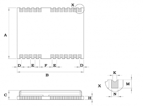
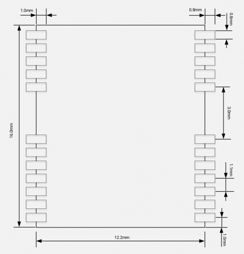
Figure 6 Dimensions
Table 12 Dimensions
| Symbol | Min.(mm) | Typ.(mm) | Max.(mm) |
|---|---|---|---|
| A | 12.0 | 12.2 | 12.4 |
| B | 15.8 | 16.0 | 16.2 |
| C | 2.2 | 2.4 | 2.6 |
| D | 0.9 | 1.0 | 1.3 |
| E | 1.0 | 1.1 | 1.2 |
| F | 2.9 | 3.0 | 3.1 |
| H | -- | 0.8 | -- |
| K | 0.4 | 0.5 | 0.6 |
| M | 0.8 | 0.9 | 1.0 |
| N | 0.7 | 0.8 | 0.9 |
6.REFERENCE DESIGN
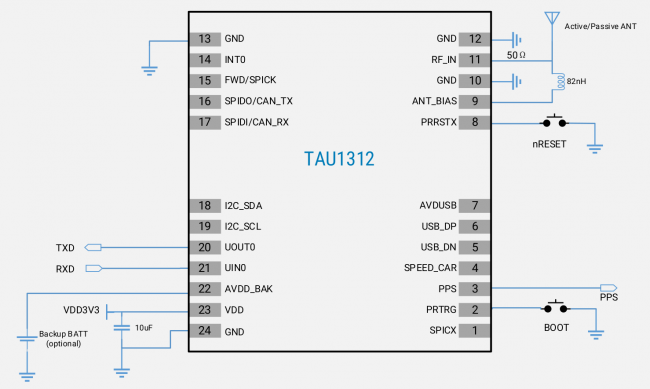
Minimal design
This is a minimal design for TAU1312 GNSS module. The 82nH inductor is used only when an active antenna is connected, and no need with a passive antenna. The characteristic impedance from RF_IN pin to the antenna connector should be 50Ω.
PCB Footprint Reference
Layout
(1) A decoupling capacitor should be placed close to VDD pin of the module, and the width of power routing should be more than 0.5mm.
(2) The width of RF routing between RF port to antenna interface should be wider than 0.2mm. The characteristic impedance of RF routing between RF port to antenna interface should be controlled to 50Ω.
(3) It is recommended that the routing from RF port to antenna interface refers to the second layer,and no routing are recommended on the layer.
(4) Do not place the module close to any EMI source, like antenna, RF routing, DC/DC or power conductor, clock signal or other high-frequency switching signal, etc.
7.PRODUCT PACKANG AND HANDLING
Packaging
Packing Notes
TAU1312 is a Moisture Sensitive Device (MSD) and Electrostatic Sensitive Device (ESD). During the packing and shipping, it is strictly required to take appropriate MSD handling instructions and precautions. The table below shows the general packing hierarchy for the standard shipment.
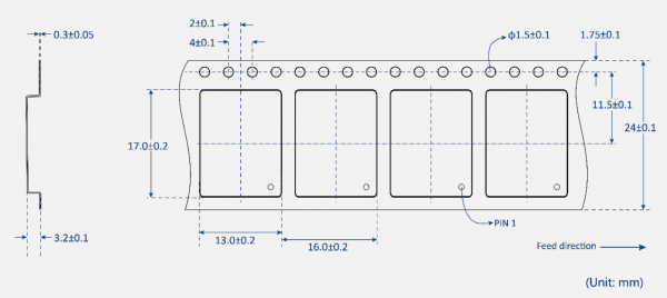
Tape and Reel
TAU1312 is delivered as hermetically sealed, reeled tapes in order to enable efficient production,production lot set-up and tear-down.
The figure below shows the tape dimensions.
TAU1312 is deliverable in quantities of 1000pcs on a reel.
Shipment Packaging
The reels of TAU1312 are packed in the sealed bags and shipped by shipping cartons. Up to five sealed bags (5000pcs in total) can be packed in one shipping carton.
Storage
In order to prevent moisture intake and protect against electrostatic discharge, TAU1312 is packaged together with a humidity indicator card and desiccant to absorb humidity.
ESD Handling Precautions
TAU1312 module which contains highly sensitive electronic circuitry is an Electrostatic-sensitive Device (ESD). Observe precautions for handling! Failure to observe these precautions can result in severe damage to the GNSS module!
- Unless there is a galvanic coupling between the local GND (i.e. the workbench) and the PCB GND,then the first point of contact when handling the PCB must always be between the local GND and PCB GND.
- Before mounting an antenna patch, connect ground of the device.
- When handling the RF pin, do not come into contact with any charged capacitors and be careful when contacting materials that can develop charges (e.g. patch antenna ~10 pF, coax cable ~50 – 80 pF/m, soldering iron, …)
- To prevent electrostatic discharge through the RF input, do not touch any exposed antenna area.If there is any risk that such exposed antenna area is touched in non ESD protected work area, implement proper ESD protection measures in the design.
- When soldering RF connectors and patch antennas to the receiver’s RF pin, make sure to use an ESD safe soldering iron (tip).
ESD protection measures
TAU1312 GNSS positioning module is sensitive to static electricity. Whenever handling it, particular care must be exercised to reduce the risk of electrostatic charges.
In addition to standard ESD safety practices, the following measures should be taken into account.
- Add ESD Diodes to the RF input part to prevent electrostatics discharge.
- Do not touch any exposed antenna area.
- Add ESD Diodes to the UART interface.
Moisture sensitivity level
The Moisture Sensitivity Level (MSL) of the GNSS module is MSL4.
8.LABELING AND ORDERING INFORMATION
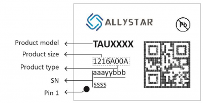
Labeling and ordering information help customers get more about Allystar products.
Labeling
8.Resource
- TAU1312 Datasheet
- Quick Start with Satrack
- ALLYSTAR_GNSS_Binary_Protocol
- NMEA_Protocol_Specification
- Download Satrack
